Step by step motor controlling
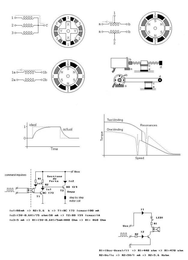
First of all a few things about step by step motors: The step by step motor is designed for precise and accurate linear and rotation movements. You can control the rotation angle in very wide limits. There are a lot of step by step motors types in industry and in a lot of domestic application. It is very easy to modify the number of revolutions, between two limits, simply by modifying the supply frequency. The step by step motor don’t use much energy, they have normally permanent magnets in their construction. There are also disadvantages: the resonance phenomena, the difference between the ideal and the real power supply signal. To avoid the first one it is normally used a switching between two and one winding or it is used a mechanical solution as shown.
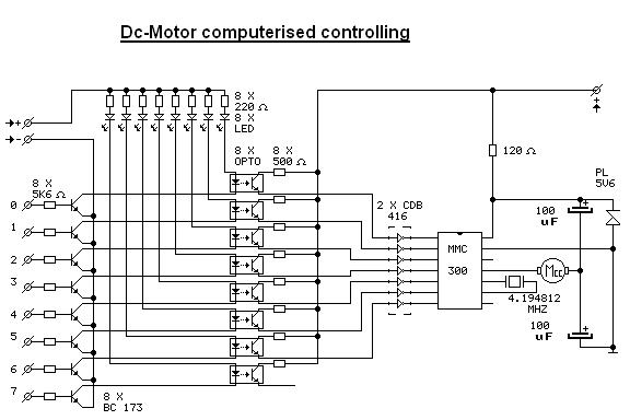
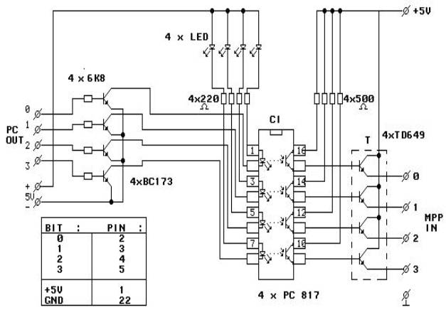
Electrical schematic:
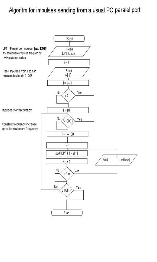
The Programming algorithms:
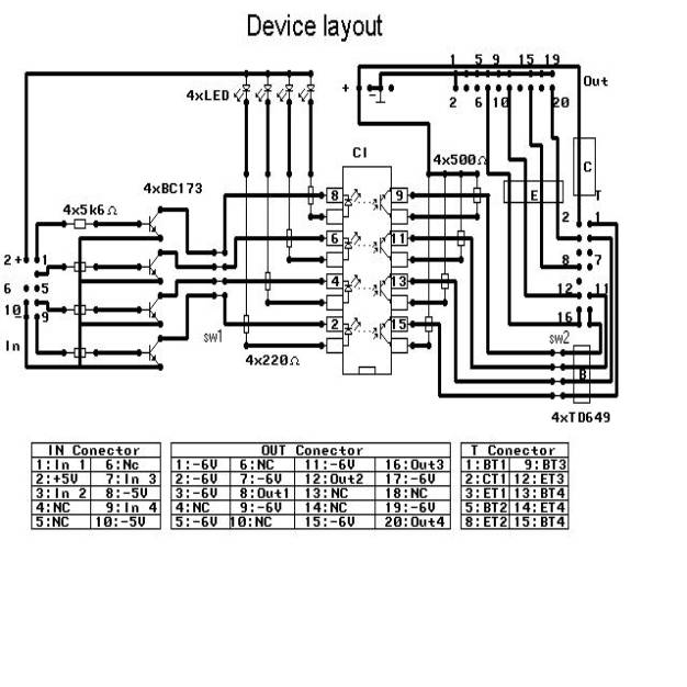
The device layout:
Next are some important PC parallel port information’s presented:
Table 1
Pin nr. Type D25 |
Pin nr. Centronics |
SPP Signal |
Direction |
Register type |
Hardware inversion |
1 |
1 |
nStrobe |
In / Out |
control |
Yes |
2 |
2 |
Data 0 |
In / Out |
date |
No |
3 |
3 |
Data 1 |
Out |
date |
No |
4 |
4 |
Data 2 |
Out |
date |
No |
5 |
5 |
Data 3 |
Out |
date |
No |
6 |
6 |
Data 4 |
Out |
date |
No |
7 |
7 |
Data 5 |
Out |
date |
No |
8 |
8 |
Data 6 |
Out |
date |
No |
9 |
9 |
Data 7 |
Out |
date |
No |
10 |
10 |
nAck |
In |
state |
No |
11 |
11 |
Busy |
In |
state |
Yes |
12 |
12 |
PaperOut(End) |
In |
state |
No |
13 |
13 |
Select |
In |
state |
No |
14 |
14 |
nAuto-LineFeed |
In / Out |
control |
Yes |
15 |
32 |
nError/Foult |
In |
state |
No |
16 |
31 |
nInitialize |
In / Out |
control |
No |
17 |
36 |
nSelect-Printer/nSelectIn |
In / Out |
control |
Yes |
18-25 |
19-30 |
Ground |
Gnd |
gnd |
no |
Table 2
Adress |
Observations |
3BCh-3BFh |
Video cards addresses |
378h-37Fh |
Usual LPT 1 address |
278h-27Fh |
Usual LPT 2 address |
Parallel port programming with Turbo
Pascal
program prog1;{program pentru detectarea
porturilor paralele}
uses crt;
var
i:integer;
baza,x:word;
jj:string[16];
function hexa(b:integer):string;
var p,r:integer;
j:array[0..15] of string[1];
begin for p:= 15 downto 0 do
begin r:=b mod 16;
case r of 0..9: str(r:1,j[p]);
10: j[p]:='A';
11: j[p]:='B';
12: j[p]:='C';
13: j[p]:='D';
14: j[p]:='E';
15: j[p]:='F';
end;
b:=b div 16;
end;
jj:='';
for p:= 0 to 15 do jj:=jj+j[p];
while jj[1]='0' do
jj:=copy(jj,2,length(jj)-1);
hexa:=jj;
end;
begin
clrscr;
for i := 0 to 3 do
begin
x:=$408+2*i;
baza:=memw[0:x];
if baza = 0 then writeln('Nu a fost
detectat nici un port la adresa 0: ',hexa(x),' h')
else writeln('Adresa portului LPT
',I+1:1,' este ',hexa(baza),' h');
end;
readln;
end.
Table 3
Memory location adress |
Semnification |
0000:0408h |
LPT 1 |
0000:040Ah |
LPT 2 |
0000:040Ch |
LPT 3 |
0000:040Eh |
LPT 4 |
How to detect if your Computer’s port
is bidirectional:
program prog2;
uses crt;
var m1,m2 : byte;
begin clrscr;
{ lpt1 $378=baza}
port[$378+0]:=0;
port[$378+2]:=0;
writeln(‘First measuremen with
MAVO’);
readln;
port[$378+0]:=32;
writeln(‘The second measurement with
MAVO’);
readln;end.
readln;end.
Table 4 SPP register SPP and their
semnification
Offset |
Register |
Read/Write |
Bit nr. |
Utilisation |
|
|
|
7 |
Data 7 |
|
|
|
6 |
Data 6 |
|
|
|
5 |
Data 5 |
Baza +0 |
date |
Write |
4 |
Data 4 |
|
|
|
3 |
Data 3 |
|
|
|
2 |
Data 2 |
|
|
|
1 |
Data 1 |
|
|
|
0 |
Data 0 |
|
|
|
7 |
Busy |
|
|
|
6 |
Ack |
|
|
|
5 |
Paper Out |
|
|
|
4 |
Select In |
Baza +1 |
state |
Read Only |
3 |
Error |
|
|
|
2 |
IRQ (not) |
|
|
|
1 |
rez |
|
|
|
0 |
rezerved |
|
|
|
7 |
nc |
|
|
|
6 |
nc |
|
|
|
5 |
Activate the port as
bidirectional |
|
|
|
4 |
Activate the IRQ through
Ack |
Baza +2 |
de control |
Read/write |
3 |
Printer Select |
|
|
|
2 |
Auto Line Feed |
|
|
|
1 |
Strobe |
|
|
|
0 |
|
Table 5
Bit 7 |
Bit 6 |
Bit 5 |
Bit 4 |
Bit 3 |
Bit 2 |
Bit 1 |
Bit 0 |
128 |
64 |
32 |
16 |
8 |
4 |
2 |
1 |
{Paralel port bit detection}
program prog3;
uses crt;
var b,i,l,m,n,o,p,m1,m2,x:byte;
j:array[0..7] of byte;
procedure binar(b,x,y :integer);
begin
gotoxy(x,y);
for p:=7 downto 0 do
begin j[p]:=b mod 2;
b:=b div 2;
end;
for p:=0 to 7 do
begin write(j[p]:1);
end;
writeln;
end;
begin
clrscr;
port[$3bc+0]:=0;
delay(10);
port[$3bc+2]:=4;
delay (10);
gotoxy(32,8);
write('=== Modul SPP ===');
repeat m1:=port[$378+1];
if (m1 and 128)=128 then m1:=m1-128 else
m1:=m1+128;
m2:=port[$3bc+2];
if (m2 and 8)=8 then m2:=m2-8 else m2:=m2+8;
if (m2 and 2)=2 then m2:=m2-2 else m2:=m2+2;
if (m2 and 1)=1 then m2:=m2-1 else m2:=m2+1;
x:=m1 or m2;
gotoxy(24,11);
write('Registrul de state baza+1');
binar(m1,54,11);
gotoxy(24,12);write('Registrul de control
baza+2');
binar(m2,54,12);
gotoxy(24,10);
write('Bitul nr. ');
gotoxy(54,10);
for p:=7 downto 0 do
begin write(p:1);
end;
delay(25);
until keypressed;
end.
{Date transmision throught the paralel port}
program prog4;
uses crt;
begin clrscr;
port[$378+0]:=0;
delay(2000);
port[$378+0]:=170;
delay(2000);
port[$378+0]:=0;
end.
The final program:
{ LPT1 parallel port detection}
program prog1;
uses crt;
var
a:array[1..255] of integer;
b,n,j,i,ii:integer;
frmin,f:real;
w,baza,x:word;
jj:string[16];
label 100,200;
function hexa(b:integer):string;
var p,r:integer;
j:array[0..15] of string[1];
begin for p:= 15 downto 0 do
begin r:=b mod 16;
case r of 0..9: str(r:1,j[p]);
10: j[p]:='A';
11: j[p]:='B';
12: j[p]:='C';
13: j[p]:='D';
14: j[p]:='E';
15: j[p]:='F';
end;
b:=b div 16;
end;
jj:='';
for p:= 0 to 15 do jj:=jj+j[p];
while jj[1]='0' do
jj:=copy(jj,2,length(jj)-1);
hexa:=jj;
end;
begin
clrscr;
for i := 0 to 3 do
begin
x:=$408+2*i;
baza:=memw[0:x];
if baza = 0 then writeln(‘There
is no port detected ',
'at the adress 0: ',hexa(x),' h')
else writeln(‘LPT port adress
',I+1:1,' is ',
hexa(baza),' h');
end;
{write(‘Insert the LPT1 port
adress= ');readln(w);
write(‘Input the desired frequency [Hz]
= ');readln(f);
write(‘Input the impulses number =
');readln(n);}
w:=$378;
port[w+0]:=0;
n:=3;
b:=0;
f:=100;
frmin:=1;
f:=100*frmin;
200:
gotoxy(10,5);
write(Input the desired
frequency [Hz]= ');read(frmin);
f:=1;
for j:=1 to n do
begin
gotoxy(10,6+j);
write(‘Input impuls
',j,' = ');read(a[j]);
end;
{frmin:=10;}
repeat
for j:=1 to n do
begin
port[w+0]:=a[j];
delay(round(1000/f));
gotoxy(25,10);clreol;gotoxy(25,11);clreol;
end;
gotoxy(10,10);write('Frecventa f= ');
gotoxy(25,10);write(f:7:1,' [Hz]');
gotoxy(10,11);write('Frecventa fr= ');
gotoxy(25,11);write(frmin:7:1,' [Hz]');
if f<frmin then f:=f+1;
until keypressed;
for j:=1 to n do
begin gotoxy(10,6+j);clreol;end;
goto 200;
{if b<10000 then goto 200;
f:=0.5;
n:=3;
100:
for j:=1 to n do
begin
write(‘Input impuls
',j,' = ');readln(a[j]);
end;
port[w+1]:=0;}
{repeat
a[1]:=1;
a[2]:=2;
a[3]:=4;
for j:=1 to n do begin
port[w+0]:=a[j];
delay(round(1/f));
end;
port[w+0]:=0;
until keypressed;
port[w+0]:=0;
goto 100;}
port[w+0]:=0;
writeln(‘The programm is over. ');
end.
There is also possible to use the same procedure for a dc-motor. You just have to convert the digital signal that comes from your Pc in dc-voltage in range 0-Vmax. The conversion is made with a special IC MMC300.